The Dos and Don'ts of using an EPROM as PLA in a C64.

Disk drives, Monitors, SuperCPU etc.
banman
Member
Member
Posts: 421
Joined: Sat Jun 15, 2019 12:21 am
Contact:

Re: The Dos and Don'ts of using an EPROM as PLA in a C64.

Post by banman »

Hi eslapion,
eslapion wrote: Sun Jun 16, 2019 3:47 am Hey thanks for the comments!
banman wrote: Sun Jun 16, 2019 3:42 am These cartridges and the ROM adapters holds 8 x 8kB ROM images. That is to say a 64kB EPROM . One needs to concatenate the 8 x 8kB files into 1 x 64kB file image to then be burnt on to the EPROM.
At that point I had absolutely no idea what that meant or how do it.

...

Oh ... I finally worked out how to concatenate multiple 8kB files - use HJSplit for Windows . It makes life very easy.....and be sure to print off Sukko Perra's ROM table for jumper settings for easy manipulation of the multi cartridge. Also make sure that each game image is exactly 8kB in size when joining.
Why exactly did you need to use a software to concatenate the files ? http://www.vic20.de/html/eprom_pla_8296_und_c64.html


Hi eslapion,


My pleasure,


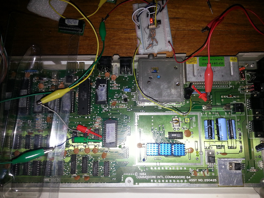
Thank you for all your patience in helping me get a working test circuit to get a clearer picture of what I was observing in these PROM based PLA's .


My apologies on the confusion on these statements.

I was referring to the original game cartridges I had set out to create. Being a complete newbie I couldn't get my head around idea of putting 8 of the 8kB games on to the single 64kB EPROM. It sounds silly I know. It took me a while to catch on. :oops: :lol:


Actually this is the site where I got the PLA.bin files to create my EPROM based PLA .

http://www.vic20.de/html/eprom_pla_8296_und_c64.html


This site has a circuit wiring diagram one can use .


The whole process of EPROM based PLA construction was very painless.


I got boards made up from this site:

https://oshpark.com/shared_projects/mdayhhyk

You can download the gerbers and take them to any PCB manufacturer you prefer. I also used PCBWay and found their boards a little better quality and cheaper.


By the way I don't think the timing delay capacitor is really required for the knockoff (fake) ST M27C512-90B6


I Burned a PLA.BIN with a TL866 minipro from here:

http://vic20.de/html/eprom_pla_8296_und_c64.html


That was basically it..... Just make sure that the chip's location dimples are inserted the correct way on the adapter board and the whole device with the dimple is pointing upwards on the C64 main board. That is towards the C64's RF unit.
I suggest using a 28pin socket and precision turned pins when making up the adapter board. The precision turned pins help preserve the C64's board and makes insertion easier.


I was thinking could a similar solution be used on a C16/ plus4 ?


User avatar
eslapion
Active Member
Active Member
Posts: 1216
Joined: Mon Jul 20, 2015 10:11 am
Location: Canada
Contact:

Re: The Dos and Don'ts of using an EPROM as PLA in a C64.

Post by eslapion »

banman wrote: Sun Jun 16, 2019 4:51 amI was thinking could a similar solution be used on a C16/ plus4 ?
http://www.vic20.de/Plus4.zip

Just be careful with the Plus/4. The vertical space constraint is very tight in that machine as the metal plate of the bottom of the keyboard could easily touch a PLA substitute.

The C16 has no such problem.
Socialism never took root in America because the poor see themselves not as an exploited proletariat but as temporarily embarrassed millionaires. -John Steinbeck
banman
Member
Member
Posts: 421
Joined: Sat Jun 15, 2019 12:21 am
Contact:

Re: The Dos and Don'ts of using an EPROM as PLA in a C64.

Post by banman »

Hi eslapion,

I didn't consider height restrictions. A very important consideration.

I think even some of the early C64C's which had the long board may be unsuitable for a higher PROM with adapter.

I know some of the C64C's have a heat shield that covers the entire board as well. That might also give EPROM based PLA adapters some challenges.


Do you have any side by side photos of how a PROM plus adapter compares to say one of your PLAnktons?
User avatar
eslapion
Active Member
Active Member
Posts: 1216
Joined: Mon Jul 20, 2015 10:11 am
Location: Canada
Contact:

Re: The Dos and Don'ts of using an EPROM as PLA in a C64.

Post by eslapion »

banman wrote: Mon Jun 17, 2019 11:17 amI think even some of the early C64C's which had the long board may be unsuitable for a higher PROM with adapter.
Yes, that's a problem there too. My solution was to solder the PROM directly onto a 28 pin DIP socket with rewiring, as I did with [url=http://www.amibay.com/showthread.php?81 ... -available]PLAkate[/quote].
I know some of the C64C's have a heat shield that covers the entire board as well. That might also give EPROM based PLA adapters some challenges.
Since these don't produce any heat, the metal tab intended to touch the PLA can simply but cut out.
Do you have any side by side photos of how a PROM plus adapter compares to say one of your PLAnktons?
Nope! I've never used an adapter as I was putting the PROM directly onto a socket when I was selling PLAkate.

The only exception is the adapter I've used for the various PROMs tested earlier in this thread but that's hardly a reference. This adapter is intentionally much taller than anything normal so I can tap any pins using small probes for oscilloscope or logic analyzer study.
Socialism never took root in America because the poor see themselves not as an exploited proletariat but as temporarily embarrassed millionaires. -John Steinbeck
banman
Member
Member
Posts: 421
Joined: Sat Jun 15, 2019 12:21 am
Contact:

Re: The Dos and Don'ts of using an EPROM as PLA in a C64.

Post by banman »

Hi esalpion,


Here are some links to videos I made recently testing various PLA's including a NEWLY DISCOVERED Knockoff (fake) ST M27C512-90B1 manufactured in CHINA OTP PROM on a C64 Board Assy No. 250425 board revision that appears to pass eslapion's test circuit.

These are knockoff (fake) Made in CHINA ST M27C512-90B1 OTP PROMS .

DSCF4015.JPG
DSCF4016.JPG


****************************************************C64 Board Assy No. 250425***************************************


Winbond W27C512 EPROM PLA


I am not sure if this is displaying bus contentions or not.


Testing The Ultimate PLA


Testing Knockoff ST M27C512 90B1 manufactured in CHINA PROM PLA substitute.


[attachment=0]DSCF4016.JPG[/attachment]


Note how the Winbond W27C512 EPROM PLA behaves erratically in the videos....
User avatar
eslapion
Active Member
Active Member
Posts: 1216
Joined: Mon Jul 20, 2015 10:11 am
Location: Canada
Contact:

Re: The Dos and Don'ts of using an EPROM as PLA in a C64.

Post by eslapion »

banman wrote: Tue Jun 18, 2019 2:50 amWinbond W27C512 EPROM PLA

I am not sure if this is displaying bus contentions or not.

In order to know for sure if a glitch results in a bus contention results in a potential bus contention, you have to check it with a logic analyzer.

The PLA is a sort of traffic light which signals who has access to the bus. Unlike some idiots have claimed, the PLA is NOT itself connected to the bus.

Now, you can imagine the internal 8 bit bus of the C64 as a sort of highway where half the time, the master is the CPU and the other half the master is the VIC-II. During each of these half cycles, the master is either reading or writing information to 'something', the direction of the flow is controlled by the R/!W line and the 'something' is determined by the PLA.

A glitch is an undesired signaling of the PLA where it is telling 'something wrong' to access the bus and this may or may not result in data corruption. A bus contention occurs when the PLA is accidentally telling more than one thing to access the bus. Since only one thing at a time can receive or send data with the bus master, more than one device will try to signal data onto the bus and this will cause a sort of 'tug of war' between these devices.

Past investigations of the behavior of PROMs used as PLA has shown that really bad candidates can signal all of its outputs low for brief periods of time. This can not only crash a C64, it could also cause damage to the chips ordered to signal on the bus; all the ROMs, DRAM, IO chips, color RAM and cartridges could be affected.

So the PLA could order chips in the C64 to commit suicide but the selfish prick will suffer no harm itself in doing so.
Socialism never took root in America because the poor see themselves not as an exploited proletariat but as temporarily embarrassed millionaires. -John Steinbeck
banman
Member
Member
Posts: 421
Joined: Sat Jun 15, 2019 12:21 am
Contact:

Re: The Dos and Don'ts of using an EPROM as PLA in a C64.

Post by banman »

Hi eslapion,


Thank you for that explanation on the PLA. Very easy to understand.


Well spotted in the videos by the way! You are correct. The C64 is missing 8Kb of RAM on the start up screen.

Actually it happens with all the tests. I noticed it when I first connected the EXROM jumper on the cartridge in the very first test. I too was concerned.
After some research I found that the game cartridge circuit board reserves (or removes) 8Kb from the C64's memory so that the 8Kb game on the cartridge can run on the C64 without any issues.
If the EXROM jumper is not connected the !ROML and !ROMH lines do not connect to the PLA. Reported free memory returns to normal as well.

I think it has somethink to do with Bank Switching.
https://www.c64-wiki.com/wiki/Bank_Switching.


This reminds me of my next question, something that I read somewhere on the C64's 6510 CPU.

The MOS 6510 CPU can only access 65536 memory locations. The C64 has more than that in hardware. Does the PLA assist in allowing the C64's CPU to address more than the MOS 6510 CPU's 65536 memory locations (or have I got this totally wrong)?
User avatar
eslapion
Active Member
Active Member
Posts: 1216
Joined: Mon Jul 20, 2015 10:11 am
Location: Canada
Contact:

Re: The Dos and Don'ts of using an EPROM as PLA in a C64.

Post by eslapion »

banman wrote: Wed Jun 19, 2019 4:53 amWell spotted in the videos by the way! You are correct. The C64 is missing 8Kb of RAM on the start up screen.

Actually it happens with all the tests. I noticed it when I first connected the EXROM jumper on the cartridge in the very first test. I too was concerned.
After some research I found that the game cartridge circuit board reserves (or removes) 8Kb from the C64's memory so that the 8Kb game on the cartridge can run on the C64 without any issues.
If the EXROM jumper is not connected the !ROML and !ROMH lines do not connect to the PLA. Reported free memory returns to normal as well.
Then all the tests you've performed with the 74LS279 are meaningless.

This circuit is to be used with no cartridges attached. The very purpose of this test is to check for glitches from the PLA when the ROM areas are mapped out so even the CPU cannot access them. Therefore the glitches can only result from electronic problems with the PLA, not by the VIC-II or CPU trying to access these areas.
Socialism never took root in America because the poor see themselves not as an exploited proletariat but as temporarily embarrassed millionaires. -John Steinbeck
banman
Member
Member
Posts: 421
Joined: Sat Jun 15, 2019 12:21 am
Contact:

Re: The Dos and Don'ts of using an EPROM as PLA in a C64.

Post by banman »

Hi eslapion,


Apologies for that error in the way that I was conducted the PLA glitch test. :oops:

It appears that the C64 Assy board # 250425 I initially used, is exceptionally tolerant of suspect EPROM PLA substitutes.


I have a feeling that this C64 Assy board # 250425 was what I initially used when I was utilizing the game cartridge card. I am sure I wasn't getting the results I was expecting. In fact I wasn't getting any LED lights coming on from memory!

Most probably then, that is when I tried the EXROM jumper on the game cartridge and observed results that correlated to what I was expecting.

Which is totally the wrong approach to conduct any meaningful analysis!


I appreciate all your helpful input.

I would not have gone as far as I have without it,thanks. :D

Here is a picture of the new way I wired up the C64 Board Rev # 250425 to your test circuit.

I have now configured the test circuit so that EXROM in not used.


https://postimg.cc/TKnzFYhB
Image


I ran the test on this C64 Board Rev # 250425 with the known bad Winbond W27C512 EPROM PLA substitute for approximately 3 hours today.


I did not see any lights come on in this time. I am definitely not saying it passes any test. It is just I can not get the lights to come on.


I will move this setup across to the other boards to test all the PLA substitutes I have as well as some Commodore Factory PLA's.


I will try a few of the Commodore Factory PLA's I have.


I know from just running a game cartridge in several different C64 revision numberd boards that the Winbond W27C512 EPROM PLA substitute is a bad one.

For some reason this C64 Board Rev B 250407 "Hi Pric" marked board actually works well.

When I put a game cartridge in, that I know behaves erratically on the other boards this one works well.

The C64 Board Rev B 250407 that does not have the markings "Hi Pric" printed on the circuit board, it performs badly.

To hazard a guess, this C64 Board Rev B 250407 "Hi Pric" marked board may have added circuity to make it more stable with PLA's.

I will conduct more observations on various C64 boards and post my findings shortly......
User avatar
eslapion
Active Member
Active Member
Posts: 1216
Joined: Mon Jul 20, 2015 10:11 am
Location: Canada
Contact:

Re: The Dos and Don'ts of using an EPROM as PLA in a C64.

Post by eslapion »

While all boards 250425 have the !CASRAM RC filter (comprised of R42 and C204), boards 250407 may or may not have such a apparatus depending on the version of the board and the type of PLA installed (82S100 or MOS 906114-01). Hence different potential behavior depending on the board.

When developing PLAnkton, I had to come up with a solution that works well on all boards and this made the acceptable response speed window rather narrow.

If you're going to study in detail this sort of stuff then it's no longer a matter of 'glitches or no glitches'. As I said, at this point only an oscilloscope will tell you what you want to know.

Also, the length of wiring between the point where you pick up the signal you want to study and the IC is way too long. Your wiring becomes a filter.
Socialism never took root in America because the poor see themselves not as an exploited proletariat but as temporarily embarrassed millionaires. -John Steinbeck
Post Reply Previous topicNext topic

Who is online

Users browsing this forum: No registered users and 12 guests