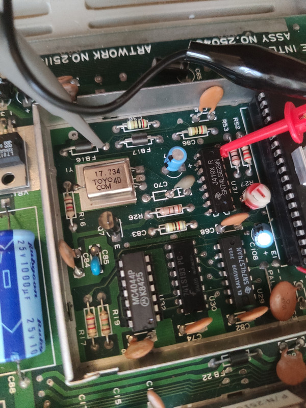
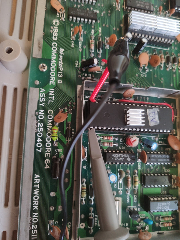
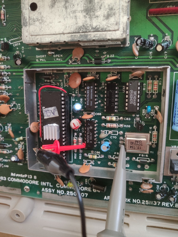
I was just looking at my ...407 board and taking a few readings.
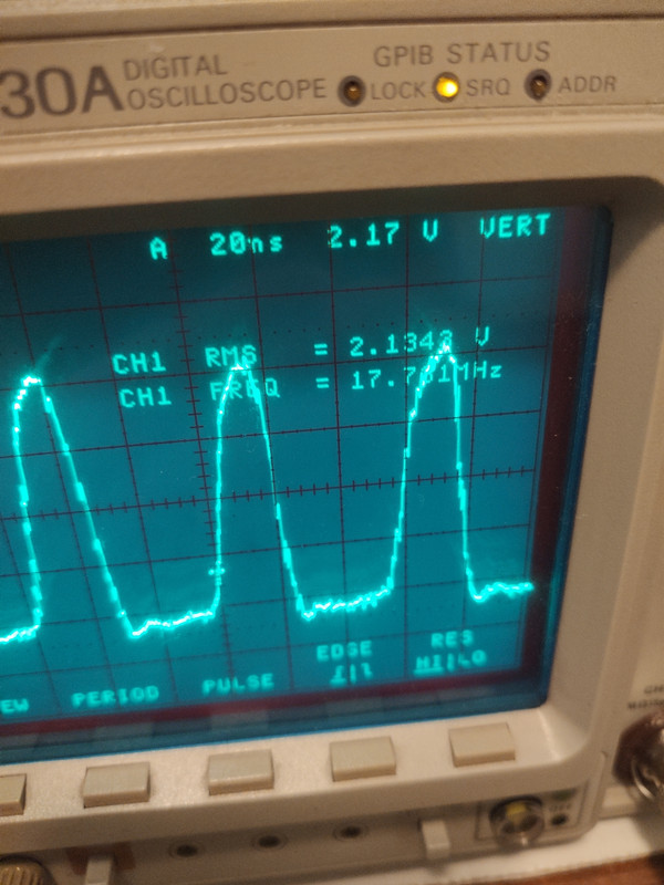
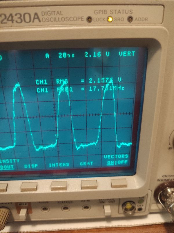
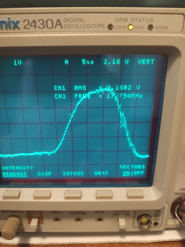
I noticed if I set my scope to just look at 1 square wave instead of say looking at multiple waves on a screen the oscilloscope is able to make much more accurate frequency readings. It still fluctuates however it is greatly improved over taking in multiple waves.
Here is what I observed.....
Apologies for the pictures being on their side. I can't seem to rotate them.
To hazard a hypothesis I would say the scope tries to average the multiple waves rather than the single wave.
I will go further (I could be wrong here) the fluctuations I see on just the single wave are actual variations on the C64's wave forming circuitry.
A suggestion you may be able to get greatly improved readings on your oscilloscope as I have if it is set to look at only 1 wave. Adjust your timebase/ sweep dial till you only see one full wave.
I noticed that in an earlier post you showed a picture of your oscilloscope's screen with lots of waves on the display. You mentioned that you were having issues with wide fluctuating readings.
It might be helpful to you, just a thought......
The pictures are from my setup. The numbers I am reading might give you a ball park figure.